MILPRF50884F
APPENDIX A
A.4.8.4.6.1 Test specimens. The printed wiring board test specimens shall be as described in appendix H.
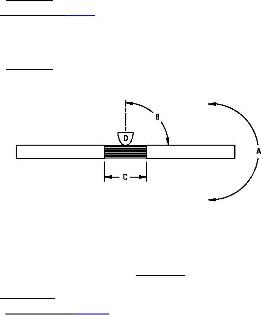
A.4.8.4.7 Folding flexibility (see A.3.7.4.7). The folding flexibility test shall be performed by subjecting the printed
wiring board test specimen to fold cycles as described below and as depicted on figure A1. The specified number of
fold cycles shall be performed with the mandrel placed in contact with the printed wiring board test specimen on one
side and then again with the mandrel placed in contact with the printed wiring board test specimen on the opposite
side. After completion of the specified number of fold cycles, both directions, the printed wiring board test specimen
shall be tested for electrical defects in accordance with A.3.7.5.1.
A.4.8.4.7.1 Test specimens. The printed wiring board test specimen shall be as described in appendix H.
NOTES:
a.
Direction of bend (detail A).
b.
Degree of bend (detail B).
c.
Points of application (detail C).
d.
Diameter of mandrel (detail D).
FIGURE A1. Folding flexibility.
A.4.8.4.8 Rework simulation.
A.4.8.4.8.1 Unsupported hole (see A.3.7.4.8.1). The printed wiring board test specimen shall be inspected in
accordance with test method number 2.4.21 of IPCTM650 with the following details and exceptions. Three holes
for each printed wiring board test specimen shall be tested. Insert wires in holes in selected lands and solder to lands
by machine or hand, as applicable. The insert wire lead shall have a diameter so that the diameter of the hole will be
at a maximum of .020 inch (0.51 mm) greater than the diameter of the inserted wire lead. The wires shall not be
clinched. It shall be considered a failure when a land around an unsupported hole is loosened.
51
For Parts Inquires submit RFQ to Parts Hangar, Inc.
© Copyright 2015 Integrated Publishing, Inc.
A Service Disabled Veteran Owned Small Business