AA59832/8
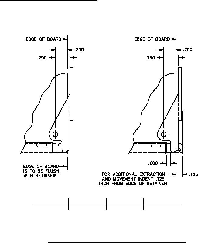
Circuit card positioning in relation to actuating surface. Two positions of a circuit card assembly edge to a locking
card guide when seated in the connector are shown on figure 9. The circuit card assembly is ejected from its
installed position by lever action of the extractor against the release tab on a locking card guide (shown) or actuating
surface of a card cage. The extractor will allow .030 inch (0.8 mm) over travel for tolerance take-up. Two extractors
mounted on each circuit card assembly is recommended.
Inches
mm
Inches
mm
Inches
mm
Inches
mm
.060
1.52
.125
3.18
.250
6.35
.290
7.37
NOTES:
1. Dimensions are in inches. Millimeter equivalents are given for general information only.
2. Unless otherwise specified, tolerances are ±.02 inch (0.51 mm) for two place decimals and ±.010 inch
(0.25 mm) for three place decimals.
FIGURE 9. Circuit card assembly to card guide dimensions (right hand extractor shown).
10
For Parts Inquires submit RFQ to Parts Hangar, Inc.
© Copyright 2015 Integrated Publishing, Inc.
A Service Disabled Veteran Owned Small Business