AA59832/8
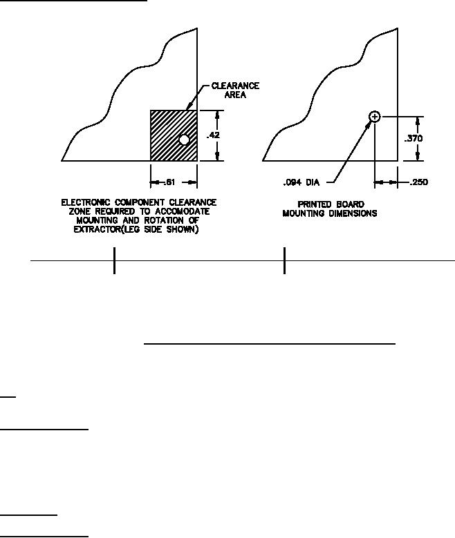
Circuit card assembly printed board. The circuit card assembly should be designed so that electronic components on
the printed board in the area around the extractor mounting hole have sufficient clearance for extractor rotation as
shown on figure 10.
Inches
mm
Inches
mm
Inches
mm
Inches
mm
Inches
mm
.094
2.39
.250
6.35
.370
9.40
.42
10.67
.61
15.49
NOTES:
1. Dimensions are in inches. Millimeter equivalents are given for general information only.
2. Unless otherwise specified, tolerances are ±.02 inch (0.51 mm) for two place decimals and ±.010 inch
(0.25 mm) for three place decimals.
FIGURE 10. Printed board clearance zone and mounting hole dimensions.
NOTES.
PIN. The PIN should be used for Government purposes to buy commercial products to this CID specification sheet.
See the classification section for PIN format example.
Source of documents.
Commercial Item Description
Extractor, Electrical Card, Metal, General Requirements For.
(Copies of these documents are available online at https://quicksearch.dla.mil.)
Ordering data. Ordering data is as specified in AA59832.
Commercial products. As part of the market analysis and research effort, this CID specification sheet was
coordinated with the following manufacturers of commercial products. At the time of CID specification sheet
preparation and coordination, these manufacturers were known to have commercial products that would meet the
requirements of this CID specification sheet. (NOTE: This information should not be considered as a list of approved
manufacturers or be used to restrict procurement to only the manufacturers shown.)
11
For Parts Inquires submit RFQ to Parts Hangar, Inc.
© Copyright 2015 Integrated Publishing, Inc.
A Service Disabled Veteran Owned Small Business