MIL-DTL-62738A(AT)
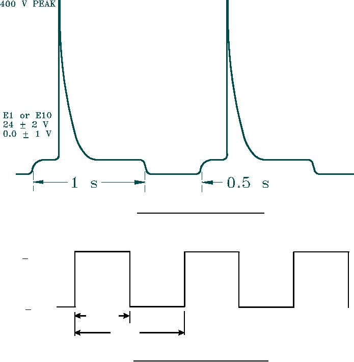
FIGURE 2. Input waveform after peak limiting.
E1 or E10
24 +2 V
0.5 + 0.2 V
0.5 to
1.0 s
1.5 s
FIGURE 3. Waveform to simulate points voltage.
13
For Parts Inquires submit RFQ to Parts Hangar, Inc.
© Copyright 2015 Integrated Publishing, Inc.
A Service Disabled Veteran Owned Small Business